Seek Thermal Imager HTC DNA Hack

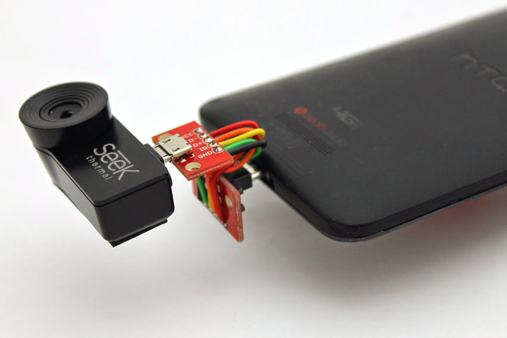
Close shot of bottom rear of HTC DNA smartphone with improvised reversing adapter attached between the phone and a Seek thermal imager add-on.

Possibly the best gift I received in 2014 was this Seek thermal add-on imager for my phone. Unfortunately, the device comes with a non-reversible micro-USB plug attached, and the single jack on my HTC Droid DNA is “upside down,” meaning the imager’s optic ends up facing the same way as the screen.

Otherwise, the thing works like a champ: app was easy to install, works well, plugged in and started up with no problems, etc. The hardware’s also pretty slick, and comes with a ruggedized keychain case so you can carry it around in your pocket. But it’s basically useless with the lens facing the wrong direction.

The Seek website recommends this six-inch male/female micro-USB extension cable for devices affected by this “backwards” problem. I bought one and it didn’t work. Again: Plug the imager directly into the phone port and it works fine; plug it in through a 6-inch USB cable—the one the manufacturer recommends—and it doesn’t. Neither the phone OS nor the imager app shows any sign of detecting the device. This was especially frustrating because the very first review on the Amazon page for this cable is titled “Works fine with the Seek Thermal.”

About this time I discovered, to my chagrin, that micro-USB extension cables come in various flavors depending on whether they are for charging/syncing the phone or allowing it to serve as a USB host (“OTG”). The hackers and engineers reading this will immediately understand my frustration at this idea—it’s an extension cable, for f*ck’s sake: All the contacts at one end should be connected to the corresponding contacts at the other end, with continuous conductors between them. Is that really too much to ask? Omitting certain conductors just serves to fragment the market and create artificial demand for multiple purchases from individual users. Nonetheless, on a lark, I bought the complementary “charging” cable and discovered that, unsurprisingly, it does not work either.

Getting really pissed off now, I hopped over to eBay and bought a US-made 6-inch micro-USB extension cable advertised as “ALL 5 WIRES CONNECTED,” which of course is what “extension cable” should mean in the first place.

Guess what? That cable didn’t work either. There was, however, now at least a glimmer of hope. Using the eBay cable, the phone OS would detect the imager’s presence just as if it were plugged directly into the port. But the imager app, itself, still showed the (now infuriatingly glib) prompt, “Connect camera to enable thermal imaging.”

Shown in the photo is what finally worked. I jumped over to SparkFun and bought matching male and female micro-USB breakout boards, then manually soldered solid-core breadboard jumper wires between the two. I did as neat a job as possible on my little homemade ribbon cable, then put a single twist in it to turn the lens in the right direction.

Now, finally, it works. But the whole experience has left me with an intense distrust of USB cables, and very impatient for the new reversible Type C micro USB connector to arrive.

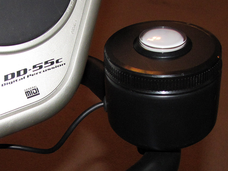
Bass drum button for drumcycle

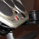
My idea of mounting a digital drum controller on a stationary bike didn’t make much of a splash when I recently posted it on Make: Projects, but for me, at least, it has been absolutely revolutionary. It makes the 30-45 minutes I spend on the bike five days a week, now, not only bearable, but actually enjoyable. It’s a step beyond “gamification” of the workout chore (or “exergaming,” if you like), because I feel like I’m not just jumping through arbitrary hoops in a game to distract myself—I’m learning an instrument. Or re-learning, anyway. I was a pretty fair drummer, in high school, and it feels great to be dusting off those skills again.

And I just upgraded it, a bit. The Yamaha DR-55c controller comes with two 1/4″ phono plugs for foot switches for “hi-hat” and “bass drum” pedals. The box included one such switch, and there’s a second port for an aftermarket add-on. Unlike the dynamically-sensitive percussion pads on the controller itself, the foot switches are simple momentary switches that do not respond with louder or softer sounds depending on how hard you hit them.

Because I’m using my feet to operate the bike pedals, however, they are not free to operate foot-switches, so I wired up a simple arcade cabinet momentary switch (the odd member of the pair I bought for my secret garage door opener project) to a 1/4″ phono plug and mounted it inside a screw-top black plastic vitamin powder container. There’s a “large” size broom clip on the bottom of the container, as well, which secures it to the bike’s handlebar. I went all out and installed a rubber grommet on the cord exit hole, too.

In practice, the arcade cabinet button is no more difficult to strike than the pads themselves, and the static volume isn’t much of an issue since the dynamic sensitivity on the pads is not all that great to begin with, especially when you’re playing without drumsticks (as I do) using the DD-55c’s “hand percussion” setting. It is mechanically much louder than the pads, however, due to the button’s “clicking” action, which detracts the system’s “quiet mode” operation: Playing just on the pads, wearing headphones, I can exercise at 3AM and not disturb anyone in the house, rocking out all the while. Add in the arcade cabinet button on the pedal trigger switch, though, and the noise could start to be a problem.

Still, it’s worked out well enough that I will probably build another one ,to almost exactly the same plan, to mount on the left handlebar. Just need to score another arcade cabinet button. Since I’ll probably have to buy one, this time, I may opt for a pair, and look for buttons that are specifically designed to operate quietly.

My standing desk setup

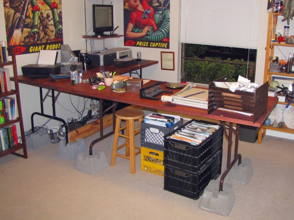
It was Nomadic Furniture that first got me interested, almost a decade ago, in the idea of working standing up. I’ve tried several times, since then, to pick up the habit, but only over the past six months, or so, have I finally made it stick.

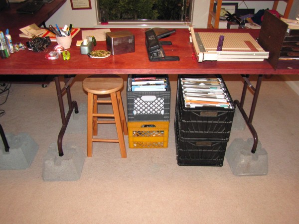
I built these two work tables from old card table legs, hollow-core doors, and extra-short molly bolts soon after moving into my current home, and published a Make: Project about it right after they were done. In spite of naysayers who believed hollow-core doors were too flimsy for this purpose, both tables have held up great, and are still going strong.

When, eight months ago, I was inspired by Mark Frauenfelder’s standing desk experiments to try it again, myself, I didn’t want to spend a lot on new furniture, or make any irreversible changes to my hollow-core door tables (which I am still quite fond of) in case it didn’t take. I had four of these cement “Dek Blocks” on hand for another project, and I decided to try simply setting one under each table leg, which had the effect of raising the work surface by about 6″, to 35″. This proved to be a very comfortable working height for me. Getting the monitor up to eye level on a wall-mounted shelf was also a critical change.

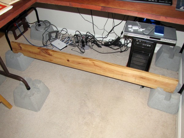
I have also found, per Benjamin Palmer’s suggestions as quoted in Mark’s follow-on post, that a barroom-style footrest or -rail is helpful for long term comfort, and the Dek Blocks also, by happy accident, provide a convenient means for adding one, as shown: Just slot a 2×6 (or other 2x nominal-dimension lumber) into the promolded slots in the front pair of Dek Blocks. Between the grooves in the blocks and the table legs themselves, gravity alone is sufficient to secure a footrail, which can simply be lifted away as necessary, e.g. for cleaning or maintenance access.

I now comfortably work from a standing position about eight hours a day, five days a week, and find it noticeably improves my attention span, energy level, mood, and overall health. There was some discomfort during the adjustment period, but, being a bit older and wiser this time, I didn’t try to just throw out my chairs and go from sitting all day to standing all day all at once. Rather, I worked up to it, starting out at just two hours in the morning, then going all morning until lunch (for awhile), and from there to standing up, all day, from 8AM to 5PM, except during my lunch hour. Done piecemeal like this, the transition was not uncomfortable at all.

Using a kitchen canister as a small trashcan

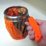
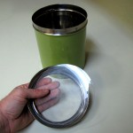
Last weekend I celebrated my birthday with a small party. There was a buffet, and we needed a wee tabletop trash can for grape stems, toothpicks, used napkins, marijuana seeds olive pits, and so forth. This was my handy-dandy improvisation: pop the acrylic top out of the lid (they’re just press-fit on the cheap canisters), pop in a plastic grocery bag, cuff it over, replace the canister rim, and, just for looks, cut around the bottom of the rim to remove excess plastic.

Homemade Toshiba TLP-671 video projector wall mount

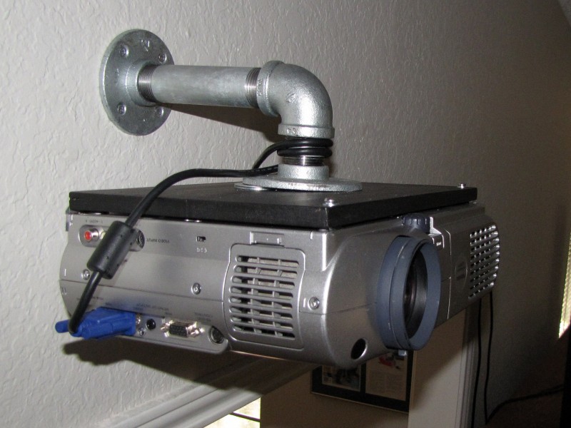
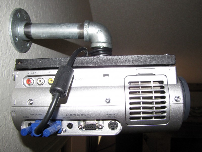
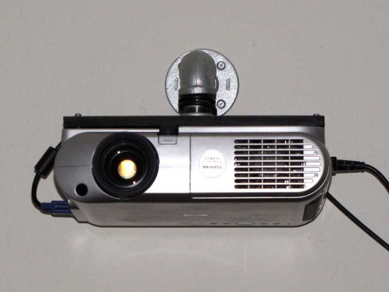
The mounting plate itself is built from a piece of 1/2″ MDF. I traced around the bottom of the projector, cut it to shape using a sabre saw, drilled the holes, rounded the corners and edges with a file, and applied a couple coats of black spray paint. Four holes in the center of the plate are fit with T-nuts, on the underside, to receive flat-head bolts passing through the horizontal pipe flange. Two holes in the front corners of the plate allow attachment by machine screws into threaded hard-points in the bottom of the projector case (which is the top, in this configuration, because the projector is mounted upside-down).

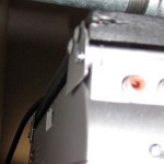
The back edge of the projector is secured by small aluminum binding triangles, shown in a detail photograph in the gallery, below. Each triangle has three screws—two with “wood” threads that secure the triangle to the back edge of the mounting plate, and one with “machine” threads that mate with threaded hard-points in the back side of the projector case.

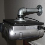
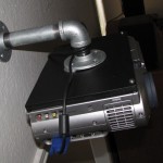
The mounting arm, obviously, is made from pipe fittings. I believe these are nominal 1.5″ diameter. The horizontal flange is connected to a 90-degree elbow by a short nipple. The elbow, from there, is connected to a longer nipple and then to a second, vertical pipe flange which is secured to a wall stud with wood screws. Power and video cables are would ’round the mounting arm for strain relief on the connectors before running off to the wall outlet and the video source.

The mounting operation consisted of 1) attaching the mounting plate to the video projector, 2) attaching the mounting arm to the wall, 3) attaching the mounting plate with projector to the mounting arm at the horizontal flange, and 4) attaching the running the cables. The only major drawback of this design is that it does not easily allow for adjustment of “pitch.” As can be seen, a pair of fender washers “shims” had to be interposed between the back edge of the horizontal pipe flange, and the mounting plate, to lower the back end of the projector and raise the image projected on the opposite wall. Otherwise, the mount has worked out just as I’d intended.

Lens cap clip mod

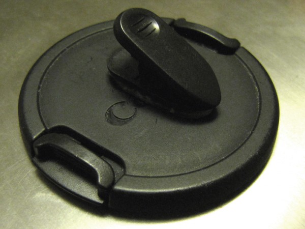
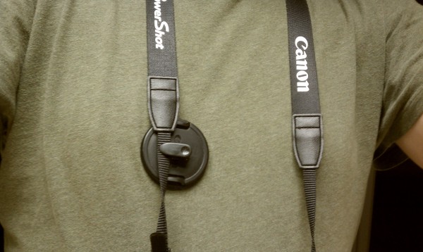
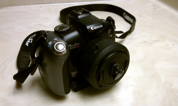
Inspired by The Nice Clip’s recent successful Kickstarter, I modified the lens cap for my Canon SX10 by sticking a small lapel clip to it with Loctite-brand outdoor mounting tape (chosen over regular double-sided foam tape for additional strength). The lapel clip was a junk box find, removed from the cord on a freebie wired headset that came bundled with a long-dead cell phone. The metal clip on one of those clear vinyl ID badge holders would also probably work.

How I modded my Xbox 360 to run 10 degrees cooler

Briefly, I did the three things suggested by ClickClick 5:

  1. Rewired one of the two fans to run at a constant 12V.
  2. Installed a small heat-sink on the graphics coprocessor.
  3. Added an aluminum foil duct over the processor heat-sink.

The hardest part of the entire process was getting the Xbox itself open, which I did by carefully following iFixit’s excellent teardown.

Rewiring the fans

This may or may not have any effect. Initially, my understanding was that the Xbox 360 fans are not run at full voltage/speed all the time, but that the driving voltage is dynamically varied depending on the console’s internal temperature. The idea behind rewiring one or both of the fans to a constant 12V source is to forgo this dynamic temperature control and just run the fan(s) at full speed all the time.

This rewiring job was easy enough. Instead of soldering to the motherboard (as ClickClick 5 does), I just spliced a short wire jumper between the fan power cable and the DVD-R power cable (which provides a constant 12V) using small wire nuts. I had to cut one wire in the DVD-R cable and one on the fan, and strip three wire ends (both ends of the cut DVD-R wire and one end of the cut fan wire), but no soldering was required. The nice part about doing it this way is that the parts you modify—the DVD-R cable and the case fan—are easy to replace if you mess up or for other reasons want to restore things to their original condition. Like ClickClick 5, I only modified one of the two fans in this way, but it would be straightforward to do them both.

However, I am not entirely sure that the Xbox does, in fact, dynamically adjust the speed of the fans. Per speedy22’s measurements of the motherboard fan connections, “V+ Starts at +5.4 VDC and climbs to +11.8 VDC within 30 sec of power on.” Which suggests that the fans may be running at 12V pretty much all the time already, and that the cooling effects both ClickClick 5 and I have measured is due only to the other two parts of his mod.

If I were to do it again, I might forego the whole splicing operation and just pop in aftermarket fans rated to move a higher volume of air than the OEM fans.

Installing a heat-sink on the graphics coprocessor

This chip is small (about 20mm square), and I didn’t have a small enough heat-sink on hand. I did, however, have an old cheap graphics card in my junk box with a ~50mm square heat-sink, which I pried off and cut down to size using a fine-tooth hacksaw blade. Aluminum is easy to work this way. I cleaned the top of the chip and the bottom of the heat-sink with Goo-Gone, followed by 91% rubbing alcohol on a cotton swab.

I had some old unopened tubes of Arctic thermal adhesive that I intended to use to secure the heat-sink in place, but when I opened them I discovered they had turned to rock on the shelf. So I substituted a drop of thin cyanoacrylate super glue, which seems to have worked out just fine.

In this case, too, it is impossible to separate the effect of this modification from the other two modifications I performed at the same time, and it would probably have been smarter to do them one at a time. The 360 case is such a PITA to open, however, that I didn’t want to mess with cracking it open and closing it up any more often than I had to.

Adding an aluminum foil duct over the processor heat-sink

This is by far the simplest of the three mods, and in retrospect I wonder whether it might not also be the most effective. Quite simply, it amounts to Scotch-taping a small rectangle of aluminum foil (shiny side down) to the plastic fan duct, so that the foil extends over the junction between the duct and the heat sink, and further about halfway along the length of the heat sink itself. The idea is that partially covering the grooves in the heat-sink forces the cooling air to be drawn more from the front of the case, thereby moving more air across the heat-sink’s cooling fins, and at higher speeds.

If I were to do all this again, I would start with this mod, reassemble the Xbox, and measure the effect before bothering with the other two mods above.

Measuring the effects

I had on hand a cheap digital indoor/outdoor thermometer. It is battery operated, with one thermistor-based temperature sensor on a 6-foot wire lead. The idea is, you set the unit on your windowsill and run the remote temperature sensor outside the window. The readout on the unit then reports the outside temperature from the probe, and the indoor temperature from a second sensor which is integral to the case.

The tip of the remote temperature sensor wedged nicely into one of the holes in the grille covering the fans on the back of the Xbox case, right in the path of the outgoing vent air. All I had to do was make sure I took all my measurements with it wedged in the same hole to be confident of fairly consistent readings. I draped the lead across the tabletop as far as it would reach and into a clear plastic peanut butter jar where I kept the temperature readout with its internal sensor. This was my room temperature reference point.

My Xbox is on almost all the time. I took seventeen measurements of the vent air temperature and the room air temperature at pseudorandom intervals over the course of about three weeks. Over these measurements, the average vent air temperature was 102 +/- 1 degrees F, the average room temperature was 76 +/- 1 degrees F, and the average overtemperature was 26 +/- 1 degrees F.

After performing the three modifications described here, I took another fourteen measurements at pseudorandom intervals over the course of about two weeks. Over these measurements, the average vent air temperature was 90 +/- 1 degrees F, the average room temperature was 73 +/- 1 degrees F, and the average overtemperature was 17 +/- 1 degrees F.

These three mods, in other words, resulted in a vent air temperature 9 +/- 1 degrees F cooler, on average, than my OEM Xbox.

Anecdotally, this cooling effect was accompanied by a marked performance improvement during processing-intensive gameplay.

Improvised cigarette butt receptacle

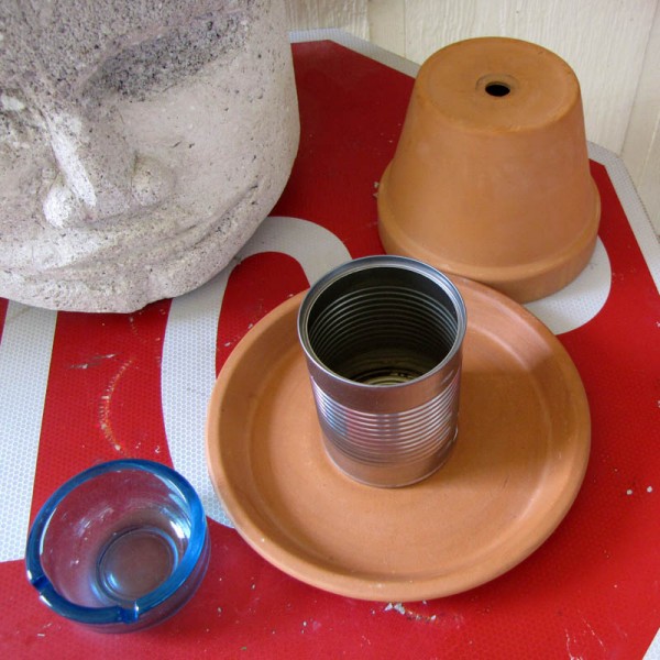
I don’t smoke, but my housemate does, and so do many of my friends, and besides the unsightliness of loose cigarette butts (either in an ashtray or on the ground), there’s also a significant risk of wildfire in my area at this time of year. This is just stuff I had lying around: a terracotta flowerpot and saucer, a soup can, and an heirloom ashtray. When you’re done smoking, you just pick up the ashtray, drop the butt in the hole, and put the ashtray back. The butt falls in the soup can inside the pot. On trash day you remove the flowerpot and empty the can into the bag. It works well, looks good, and is easy to do.